USB Unit for Resistance and Temperature Measurement, Counting and Control
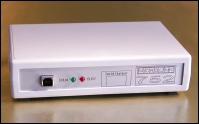
The Microlink 752 unit plugs into the computer's USB port and provides differential inputs to monitor resistance, RTDs, Pt100 probes and voltage signals. The units also offer digital input and output, counting, and voltage or current output control. You can connect 8 USB units to 1 PC.
Features
- Monitor resistance, temperature and voltage through 16 differential analogue input channels
- Handles RTDs and Pt100 probes
- Switch up to 24 digital outputs
- Monitor up to 24 digital inputs
- Count events with up to 8 counters
- Control 2 voltage or current analogue outputs
- With extra hardware monitor thermocouples and strain gauge bridges
- Includes the powerful yet easy-to-use Windmill measurement and control software for Windows
- Laptop, desktop, networked and mobile data acquisition
- Powered from the PC
- Low power consumption
- Connect up to 8 Microlink 752 units to one PC
- Choice of four analogue input ranges, selected with Windmill software individually for each channel
- Alternatively, choose automatic ranging and let the software match the input signal as closely as possible
- Integrating analogue-to-digital converter reduces electrical noise
- Use Windmill to select the resolution of the A-D converter (from 12- to 18-bits): choose high throughput or high resolution
- Automatic recalibration
- All results presented in engineering units (oC, oF, etc)
- The system supports 2 wire, 3 wire, 4 wire and 4 wire compensated resistance measurement.
- Free technical support for life
Resistance, RTD, PRT and Pt100 Measurements
Resistance measurements are made by passing a constant, known, current through the unknown resistance, and monitoring the voltage drop across the resistance. The 752 unit has a constant current source of 1 milliamp.
When the resistance to be measured is small, the resistance in the leads to the sensors can significantly affect accuracy. However, different wiring configurations allow the lead resistance to be measured and compensated for. The Microlink 752 gives excellent results for all configurations, including 2 wire, 3 wire, 4 wire and 4 wire compensated. The most accurate results are obtained using a 4 wire arrangement. More connections are required for these arrangements than for straightforward voltage measurement. This means that you can monitor 16 voltages or 8 resistances, or a combination of the two such as 8 voltages and 4 resistances.
RTDs rely on the principle that the resistance of a metal increases with temperature. For extreme precision, the resistance element is made of platinum and the RTD known as a platinum resistance thermometer (PRT). When specified to have a resistance of 100 Ohm at 0 oC, RTDs are referred to as Pt100 probes. Windmill automatically converts the resistance measurement to a temperature in your choice of engineering units.
The resolution of measurements is set through Windmill software. You can choose from 12 to 18 bits: for fast speeds or high resolution. There are 4 input ranges on offer, and Windmill can automatically select the range most closely encompassing the signals.
Digital Inputs and Outputs
The 752 provides 24 digital I/O lines, arranged in three ports, or groups, of 8. Use Windmill to choose whether each port is an input or an output. You can read or set the state of each line individually. Alternatively, you can switch several channels at the same time.
Counters
The Microlink 752 has eight 16-bit totalling counters. Each counter starts at zero and counts pulses to a maximum of 65535. You can reset a counter at any time from Windmill software. You can use the counters in two modes: accumulating count and resetting count. In accumulating count the counter keeps counting until you reset it. In resetting count the counter shows the number of pulses since the last reading.
You can set a scale and offset factor to the count from software. For example if the pulses came from a flow meter which produced one pulse for every 50 millilitres, a scale factor of 0.05 would give a reading in litres.
The counters are found on 8 of the digital input and output lines. You can use any of these you don't need for counting as normal digital inputs: the counts are always maintained even if you don't plan to use them.
Thermocouples and Strain Gauges
By adding a Microlink 593 unit, which provides cold junction measurement, you can also monitor thermocouples. For strain gauges you need a Microlink 594 connection box and excitation supply.
Signal Connections
The slim Microlink 752 provides pin connections for your signals. However, if you prefer to use screw-terminals these are provided by our Microlink 590 unit. This also allows many extra facilities, such as:
- contact closure inputs
- higher voltage inputs than normal
- input protection from high voltages
- external current source switching
- output protection
Software
The latest version of Windmill is supplied with the Microlink 752. This modular suite offers data logging, charting, alarm indication, output control, process mimic generators, sequence control, programming tools and many other modules.
Ordering
The Microlink 752 package starts at 955 pounds. You can order over the internet through Windmill Software's Data Acquisition and Control Catalogue. Alternatively ask us for a quotation for the Microlink 752. Please give as many details as possible about your application: including the number and type of transducers to be monitored. You can also use the quote form simply to ask our advice about your project.
Hardware Specifications
Dimensions (mm)             180 x 120 x 40
Maximum length of cable     5 m
  Maximum distance from PC can be increased by
  use of USB hubs
ANALOGUE INPUTS
  Current source            1 milliampere
  Maximum resistance inputs 8
  Maximum voltage inputs    16
  Maximum safe input voltage:
  Power supply on           ±48 V
  Power supply off          ±33 V
  Transient                 ±300 V
  Analogue to Digital Converter:
  Maximum linearity error   ±0.02%
  Resolution    Integration Time    Samples/Second
  12 bits         2.5 msec          80
  13 bits         5 msec            64
  14 bits        10 msec            48
  15 bits        20 msec            32
  16 bits        40 msec            16
  18 bits       160 msec             6
ANALOGUE OUTPUTS
  Max # analogue outputs    2
  Voltage output            0-10.240 V
  Max # voltage outputs     2
  Current output            0-20.480 mA
  Max # current outputs     2
  Resolution                12 bits
DIGITAL INPUTS/OUTPUTS
  Maximum number inputs     24
  Maximum number outputs    24
  (selected through Windmill in ports of 8 lines)
  Power-up state            all inputs
  Compatibility             TTL and 5 V CMOS, can be made
                            contact closure compatible
  Range                     0 to 5 V
  Output capability         15 LSTLL loads
  Maximum I/O speed         160 channels per second
COUNTERS
  Maximum number counters   8
  Resolution                16 bits
  Compatibility             TTL, 5 V CMOS, can be made
                            contact closure compatible
  Input voltage range       0 to 5 V
  Maximum count speed       160 counts per second
