The rate at which you need to sample an analogue signal, to get a good digital representation, depends on how fast the signal is changing. For faster signals this will be determined from the maximum frequency component in the signal, but for slowly changing signals from industrial plants you can use the maximum expected rate of change.
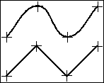
For frequency components the Nyquist theorem demands that the signal be sampled at least twice in each cycle, otherwise the amplitude of this frequency component will distort the signal at lower frequencies. So, sample at least twice as fast as the highest significant component. This rate would not mimic the waveform very closely though.

Angular waveform produced when the signal is sampled at twice its highest frequency.
To get an accurate picture of the waveform you will need a sampling rate of 10 to 20 times the highest frequency.
For slowly changing, essentially DC, signals, then all that is necessary is to consider the minimum time for a significant change in the signal.
Multiple Analogue Signals
There are two approaches to digitising multiple analogue signals. One is to use an analogue-to-digital converter for each input. Providing sampling is initiated from a single clock source, this method permits simultaneous sampling, and ensures that there is no reduction in sampling rate as the number of inputs is increased.
The second approach is to use a single analogue-to-digital converter and switch each signal in turn to the converter. This multiplexing method is much cheaper to implement but it does not provide simultaneous sampling across the inputs, and as more inputs are added the maximum sampling rate is reduced per input.
High Speed Multiplexing
- Clocked Sampling
- When recording signal waveforms, or where accurate timing measurements need to be made, the clock interrupts generated by a personal computer may not be accurate enough. In this case an external, crystal controlled clock, can generate regular clock pulses, which trigger an A/D conversion. By using the clock pulse to step round the input channels, the clock can also control the multiplexing of multiple inputs.
- Scanning: Stepping Round the Analogue Inputs
- Normal channel scanning involves stepping round each channel at equal intervals (the inter-channel interval). The scan will get round to the first channel again once all the channels in the scan have been sampled: this time defines the scan interval. Because the multiplexer switches the input voltage to the analogue-to-digital converter, time must be allowed for the voltage to settle to the new value. This defines a minimum inter-channel interval; if you try to go faster than this there will be increasing cross-talk between channels.
Low-level signals, such as thermocouple voltages, will take longer than higher voltage signals to settle to their true values. It is good practice to group signal sizes if possible.
- Channel Sub-Sets
- Because you may have many analogue signals connected to your measurement system, the ability to select a subset to scan at high speed is important to avoid having to rewire your connections each time you want to record some waveform data.
- Split-Rate Scanning
- If you are monitoring an engine, recording pressure signals from the cylinders and coolant temperatures, it is sensible to record the pressure signals much more often than the coolant temperature. This leads to the idea of split-rate scanning, where a sub-set of channels is recorded every scan, whilst all channels are recorded every nth scan.
![]() Home
Home
![]() Index
Index
![]() Technical Notes Contents
Technical Notes Contents
